Static bypass and maintenance bypass: two paths, two purposes
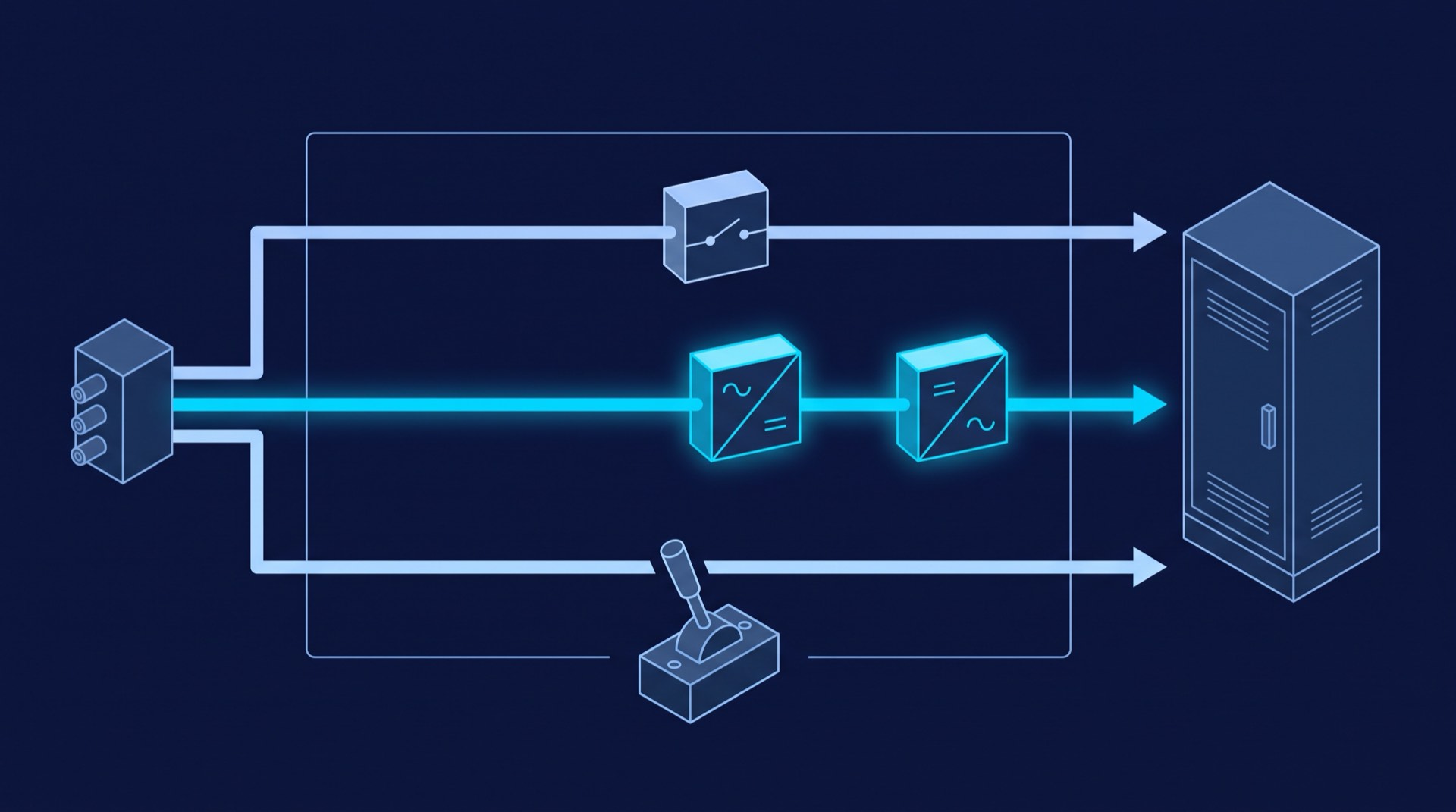
Both paths connect the load to the incoming AC supply without passing through the inverter. Everything else differs: who operates them, how fast, and what protects the load afterwards.
- Static bypass — automatic, solid-state, unattended
- A thyristor switch inside the UPS, commanded by the unit's own control. The LEON-A Series industrial UPS manual defines it in a line: the static transfer switch connects either the bypass line voltage or the inverter voltage to the output of the UPS. The EON 33 Series three-phase UPS manual names the triggers — an overload for the inverter in normal mode, or an inverter that has become abnormal.
- Maintenance bypass — manual, mechanical, attended
- A breaker or rotary switch, operated by a person, feeding the load from the bypass supply so the UPS itself can be worked on. On the EON 33 Series it is an internal maintenance bypass breaker behind a protective cover; on the LEON-A it is the K3 maintenance bypass circuit breaker, and the manual notes that with every other switch off, the load is still fed through that mechanical switch.
What the static bypass protects against, and what it does not
The static bypass answers a problem inside the UPS: an inverter that has stopped, faulted or run out of headroom. It does so by handing the load to the supply the UPS was conditioning, which removes nearly everything the UPS was bought for. It only works while that source is inside published limits: the EON 33 Series publishes a bypass voltage range of "Factory Setting; -20%~+15% (LCD Panel Selectable)" and a bypass frequency range of ±1Hz, ±3Hz, ±5Hz.
Nor is the transfer unconditionally seamless. The EON 33 datasheet publishes a transfer time of 0 ms; read literally, that is the synchronised case. Its manual supplies the other one: switching is uninterrupted if the inverter is synchronised with the bypass, but if it is unsynchronised there will be an interruption of less than 3/4 cycle — deliberate, to avoid large cross currents from paralleling unsynchronised AC sources. The LEON-A puts the same mechanism in numbers: on synchronisation loss it inserts a gap of ½ cycle, 10ms at 50Hz and 8.3ms at 60Hz. Coming back is a third figure — EON 31 publishes Bypass to INV: 0 ms and INV to Bypass: <5ms, and the EON 33 manual cautions that with the bypass frequency over its tracking range the transfer from bypass to inverter carries an interruption of less than 10ms. Weigh the unsynchronised figures against what your load can actually ride through.
The overload ladder decides when the static bypass takes the load
Overload is the most common reason a static bypass engages, and it is not a judgement call — it is a published ladder of load percentage against time. The EON 31 Series prints the consequence into the specification: 105% - 110% load - 10 mins (then Bypass), 110% - 125% Load - 1 min (then Bypass), 125% - 150% Load - 30 secs (then Bypass). Past the time limit at each rung, the inverter stops carrying the load and the static bypass carries it. Larger frames publish the ladder without the annotation: EON 33 Series inverter overload characteristics are 110% load - 60mins, 125-150% Load - 1min and 150% Load - >200ms, and the LEON-A allows 110% Load - Continuous, 110-125% Load - 10mins and 125-150% Load - 1min.
The bypass has its own, different ladder — the EON 33 Series publishes 125% - Continuous, 125%~130% - 10mins, 130%~150% - 1 min, 150%~400% - 1 sec and >400% - 200ms. An inrush that pushes the inverter off its ladder in a minute can therefore sit on the bypass continuously, which is why a chronically overloaded installation looks stable and fails when it tries to return to the inverter.
Overload is not the only trigger — over-temperature and an inverter fault do the same, and the EON 31 Series lists Over Temperature among its protections alongside Short Circuit, Over Load, Over Voltage, Low Voltage, Battery Low and Fan Failure. A blocked filter in a warm room can put a correctly sized system on bypass.
Why the load is unprotected during a maintenance bypass
A maintenance bypass makes the UPS removable by connecting the load straight to the bypass supply with the unit isolated behind it. The LEON-A manual states the consequence inside the procedure: with the load fed from the bypass network through the K3 maintenance bypass circuit breaker, any interruption in the bypass network will be reflected on your load. The ENTS Series manual says the same of its own maintenance bypass: the load is not protected against power failures.
That reframes the outage window. It is not the time an engineer spends with a cover off; it is the entire period the load runs on raw mains, during which every risk the UPS was specified to remove is live. Plan it like an outage: duration, the load's tolerance, the state of the incoming supply, and who can call a halt.
Isolated is also not de-energised. The EON 33 manual carries a DANGER notice for maintenance mode — dangerous voltages are present on the terminals of input, output and neutral, even with the LCD turned off — and the LEON-A manual says the equipment contains live voltages at all times unless it is externally isolated from the mains supply, the bypass supply and the batteries. There is deliberately no switching sequence here; it differs by model and arrangement. Take it from the unit's own manual and have it performed by a competent person — the LEON-A's wording is a competent engineer familiar with the operation and layout of the equipment who understands the areas of potential hazard.
And some work cannot be done on maintenance bypass at all: the LEON-A's check of all input and output power cables and connections requires the UPS to be completely shut down, at an interval not exceeding 2 years. That one needs a real load outage, or a second path.
Internal, external and wrap-around: what a maintenance bypass changes about redundancy
Where the bypass sits decides what can be touched. An internal maintenance bypass — the breaker behind the cover on an EON 33 — lets an engineer work on the power section with the load fed through the same cabinet, but nobody can de-energise that cabinet, open its terminals, move it or replace it. A wrap-around external maintenance bypass is separate switchgear outside the UPS: with it closed and the unit's isolators open, the UPS becomes a box that can be disconnected entirely, which is what makes a whole-unit swap possible without dropping the load. ENCLOVE's EON 33 datasheet assumes that shape for multi-unit systems, describing an N+X parallel configuration with external M. bypass.
For a single-unit installation this is the whole availability story. Without a wrap-around bypass, "the UPS is out of service" and "the load is off" are the same sentence. With one they are different sentences — but the second reads "load on raw mains". A maintenance bypass converts a hard outage into an unprotected run: a real gain in availability, none at all in protection, and not redundancy. If work has to happen while the load stays protected, the answer is a second path — the argument for N+1 and 2N UPS configurations; LEON-A units parallel up to 4 Units, as dual redundant or for capacity.
The bypass source is a separate decision. Both families can feed the bypass independently of the rectifier — the EON 33's split input for a split bypass source, the LEON-A's separate bypass input line — and each source is another isolation point: the LEON-A procedure calls for isolating the input mains externally and also the bypass supply where split bypass is in use.
The interlocks that stop a back-feed or a source clash
Two hazards shape the interlocking. One is paralleling sources that are not in step, the physics behind the gap the static bypass inserts when inverter and bypass are unsynchronised. The other is back-feed: energy arriving at terminals someone believes are dead. Good arrangements make the wrong state physically hard, not merely documented.
- Break-before-make on the manual path
- The manual bypass must not tie inverter output and bypass supply together through a closed transition. The ENTS Series publishes Break Before Make as its transfer type, and lists Bypass protection (Interlock) among its protections alongside Backfeed and Unsync protection.
- A mechanical interlock between cover and electronics
- On the EON 33 the maintenance bypass breaker sits behind a protective cover, and the two are interlocked: removing the cover transfers the system to bypass mode automatically, and the manual states it stays on bypass mode until the cover is refitted.
- Indication that cannot be misread
- The LEON-A raises Bypass Maint Closed while K3 is on, and Output CB Open when the K4 output breaker is off, noting that with K3 off the loads are then de-energised. Read the panel before touching a switch, and route the same signals to monitoring.
- Labelling and control of the switches
- The EON 33 installation instructions call for warning signs on the switches to prevent unauthorised operation — the least technical item here, and the one most often missing.
What to require in a UPS bypass specification
Most UPS bypass disappointments are specification gaps rather than equipment faults: the arrangement supplied was legitimate, it simply did not permit the work the site assumed it would.
- State whether the maintenance bypass is internal or external wrap-around switchgear, and require the list of tasks each permits with the load live — and the list that still needs a full shutdown.
- Require break-before-make behaviour on the manual path, and an interlock that makes a closed transition between inverter output and bypass supply impossible.
- Require the bypass rated for the full load continuously, and its overload ladder separately: on the EON 33 the bypass is rated 125% - Continuous through >400% - 200ms, the inverter ladder starts at 110% load - 60mins.
- Ask for transfer times in both directions and unsynchronised. EON 31 publishes Bypass to INV: 0 ms and INV to Bypass: <5ms; the EON 33 manual qualifies its 0 ms with an interruption of less than 3/4 cycle when the inverter is not synchronised.
- Decide whether the bypass supply is common with the rectifier input or a separate split-bypass feed, and require an isolation point for each source.
- Require clear indication and remote signalling of each bypass state: static bypass active, maintenance bypass closed, output isolator open.
- Require the switching procedures as a submittal, with labelling on the switches, and name who is competent to perform them on site.
How a static bypass differs from a downstream static transfer switch
Both devices switch with thyristors, both act in milliseconds, and there the resemblance ends. A static bypass chooses between two paths inside one UPS: that unit's inverter and that unit's bypass supply. A static transfer switch chooses between two independent upstream sources for a load with only one cord — one answers a fault in the UPS, the other the loss of a whole supply path, and the ATS and STS comparison covers the switch side in its own right. Read the figures separately too: the ENTS Series transfers Break Before Make in <5ms (Sync) & ~10ms (Unsync) @ 50Hz and <4ms (Sync) & ~10ms (Unsync) @ 60Hz — source to source, downstream of the UPS, not inverter to bypass inside it.
The two meet in the maintenance window. If one of the switch's sources is the UPS you are about to put on maintenance bypass, its manual addresses the case: when a source will be de-energised for hours or days, set the unit to maintenance bypass mode for the remaining source, because otherwise a failure in that source's switching components leaves no second source to transfer to and the load loses power. That spends the switch's own protection too — two devices, two maintenance bypasses, two unprotected intervals to keep from overlapping.