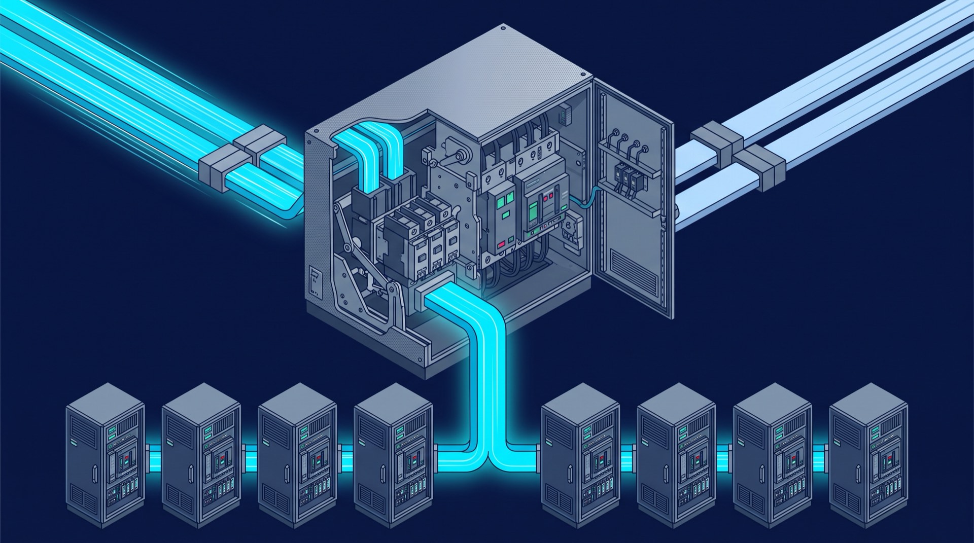
ATS vs STS: the difference that actually matters
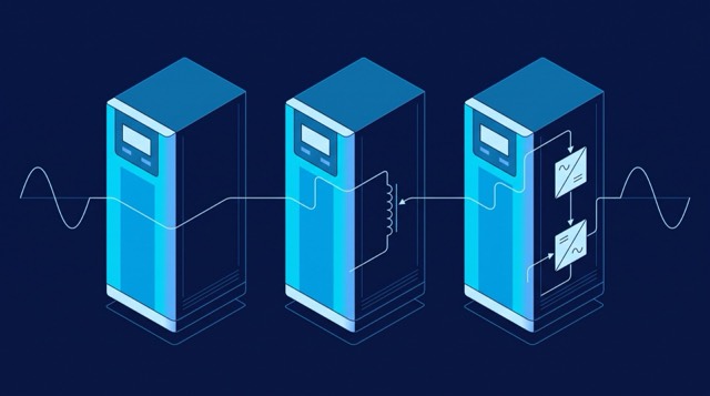
An automatic transfer switch senses that its preferred source has failed, releases the contactor or motorised breaker feeding the load, waits for the mechanism to clear, then closes onto the alternate source. Every step is mechanical, so the load experiences a genuine break in supply. The switch is not slow because it is badly designed; it is slow because metal has to travel.
A static transfer switch replaces those contacts with back-to-back thyristors, one pair per switched pole, under digital control. Nothing has to move: the controller stops firing the thyristors on the failing source and starts firing the healthy one, and a correctly applied switch does this without the load seeing an outage.
One detail surprises anyone who assumes a solid-state switch simply overlaps its sources: the ENTS datasheet lists its transfer type as "Break Before Make", exactly as an open-transition ATS does. The manual gives the reason — there must be no back-feed during supply of the load, so the two sources must never be allowed to clash, or both can end up unavailable. Both families therefore break before they make; what differs is whether the break is long enough for your load to notice.
What an automatic transfer switch is built from
The power path of an automatic transfer switch is a pair of contactors or breakers with a mechanical interlock that makes closing both at once physically impossible, plus a controller watching each source. Because those elements are electromechanical, an ATS carries current the way a breaker does: cheap per amp, good fault withstand, negligible loss while closed, and no thermal problem as frame sizes grow.
Its natural duty is the pair of sources that can never be synchronised anyway. Utility against standby generator is the classic case, and the ENCLOVE automatic transfer switch range is framed around it. The generator is not running while the utility is healthy, so no version of that transfer keeps the load energised — the set has to start and stabilise first. A faster switching element buys nothing, because the delay lives in the source, not the switch. The ENTS manual puts that same pairing on the list of sources that are not in synchronism, "like case between utility and standby generator".
An ATS is therefore the right answer more often than its reputation suggests. Lighting, heating, pumps, process ventilation, life-safety loads and battery chargers all tolerate the break it produces.
What a static transfer switch is built from
A static transfer switch is a controlled power-electronic stage rather than a mechanism. In the ENTS Series the switching elements are thyristor assemblies driven by a DSP controller, and the datasheet describes the transfer as fuseless and fully static. The series is built in 1, 2, 3 and 4-pole configurations, and its datasheet cover states the range as 16A to 1200A, with published tables running 16A to 150A in single phase and 63A to 800A in three phase.
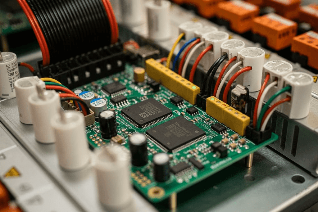
Because current passes through semiconductors rather than closed contacts, three consequences follow that an ATS does not have. First, there is conduction loss to design around: the datasheet efficiency figures run from 94% on the smallest 16A frame to 99% on the larger ones, and the bigger three-phase frames are fan forced. Second, overload capability has to be published as a time-limited ladder rather than assumed. Third, the control electronics become part of the availability calculation — which is why the ENTS Series carries up to four independent internal power supplies, so that losing one does not take the switch with it. Serviceability follows the same logic: full front access, hot-swappable power modules on the 2U systems, and an internal maintenance bypass.
How fast is a static transfer switch, and when is it not fast?
This is where most comparisons go wrong: a static transfer switch does not have one transfer time. It has two, and which you get depends on the sources rather than the switch.
When the two sources are in synchronism, the ENTS datasheet gives a transfer time of less than 5ms at 50Hz and less than 4ms at 60Hz. When they are not, it gives approximately 10ms at either frequency. The manual explains why: a 10ms time space is added into the transfer to avoid overlapping of the source voltages when the sources are not synchronous. If your feeds are not held in phase, the unsynchronised figure is the one to design against.
Detection matters as much as the transfer, and the manual describes two ways of judging a source. Fast fail detection works on the shape of the voltage waveform, catching glitches and spikes above a predefined amplitude, with a detection time the manual puts at around milliseconds. Slow fail detection works on the RMS value and needs several periods to conclude that a source is out of range. A sag that develops gradually is caught by the slower mechanism, so the load's total exposure is detection plus transfer, never transfer alone.
The windows that define "out of range" are configurable and belong in the design, not in commissioning. The ENTS voltage range is ±20% on the single-phase frames and ±15% on the three-phase frames, transferring when the source leaves that band, with an adjustable 45-65Hz frequency range that transfers on the same basis.
Which loads survive which kind of interruption
The useful question is not "how long is the break?" but "what is the shortest interruption anything on this bus cannot tolerate?" Answer that and the choice usually makes itself.
Some loads are indifferent. Resistive heating, most lighting, pumps and fans allowed to coast, and anything a control sequence will simply restart do not care that supply was momentarily absent. An ATS serves them properly and cheaply.
Others hold their state electrically. Contactor-held motor starters and control relays drop out when their coils lose supply, and a plant can be brought down not by the loss of power but by the latching sequence that has to be walked back afterwards. Servers, storage, network equipment and control processors carry only as much internal hold-up as their own power supplies provide — a property of the equipment, not something a switch can promise on its behalf. For these loads the value of a static transfer switch is not speed as an abstract virtue; it is that the interruption falls inside the load’s own tolerance, so no state is lost. Mixed boards are governed by their most sensitive load, and one such load silently sets the requirement for everything on the board.
Where each switch belongs in a dual-path design
In a well-ordered dual-path installation the two device types do not compete: they occupy different positions and solve different problems.
The automatic transfer switch belongs upstream, at the boundary between supplies that are independent in origin — utility against utility, or utility against generator. It decides which supply feeds the building or the switchboard, and its transfer is allowed to be visible because everything critical downstream sits behind something that rides through.
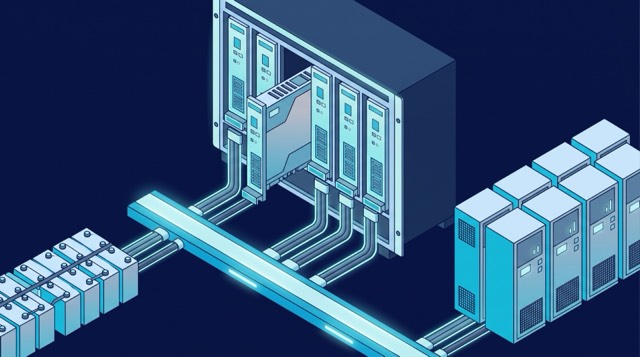
The static transfer switch belongs downstream, at the last point where the load can still be given a choice. Its most valuable job is making a dual-path facility usable by single-corded equipment: independent A and B feeds arrive, the load has one inlet, and the switch selects between them. That is the case set out on the static transfer switches page, and the reason the ENTS Series is offered both as 19-inch rack-mount units and as floor-standing cabinets. In a datacenter or telecom site an STS is typically fed from two UPS outputs or two PDU feeds; in an industrial plant, from two switchboard sections backed by different sources.
Why an STS is not a substitute for a UPS, and a UPS is not a substitute for an STS
A static transfer switch stores no energy. It selects; it does not generate. Give it two sources and it will keep the load on whichever is healthy, but if both are disturbed at the same moment there is nothing to select. Utility events are frequently common-mode, so two feeds from the same upstream network can fail together — and then an STS contributes nothing.
A UPS is the opposite. It carries stored energy and will support the load through the loss of its input, but it has one output, and a UPS being maintained or recovered from a fault takes its load with it unless something else is arranged. The two are complementary and normally sit in series: uninterruptible power supplies provide ride-through and conditioning, while the transfer switch provides path redundancy. Where the UPS itself must be made redundant, modular UPS systems and a downstream STS address different failure modes — the modular architecture covers a module failing inside one path, the transfer switch covers the loss of a whole path.
One caution from the ENTS manual belongs here, because it is the failure mode people forget. While the maintenance bypass switch sits in a source position, the load is fed through the bypass circuit breaker and is not protected against power failures. A bypass is a maintenance tool, not a mode of operation.
The selection questions to settle before you buy
Once the ATS versus STS decision is made, the specification is largely a matter of answering these in writing. Each has a wrong answer that is expensive to discover after delivery.
- How many poles, and is the neutral switched?
- The ENTS Series comes in 1, 2, 3 and 4-pole configurations, and the choice changes the earthing behaviour of the installation. Models without neutral switching bond the Source 1, Source 2 and output neutrals internally, so phase current entering from one source can return through the other source's neutral — defeating the operating principle of a residual current device. The manual states the consequence directly: on those models no RCD may be connected to the input, though one may be fitted to the output, and an input-side RCD requires a neutral-switching model.
- Will the two sources ever be in synchronism?
- This one answer determines what the switch can deliver. Synchronised sources give the ENTS Series its fastest published transfer, under 5ms at 50Hz and under 4ms at 60Hz; unsynchronised sources add the deliberate 10ms dead time. It also shapes operator procedure: the manual notes that when the sources are not synchronous a manual transfer is inhibited and delayed until they re-enter the synchronisation window, so a planned changeover may not happen on demand.
- Where does the switch sit relative to the UPS?
- Upstream of a UPS, a transfer switch feeds a load that is already protected and the UPS absorbs the transfer. Downstream of two UPS units it is the last line of defence and its own reliability becomes the availability of the load — which is what justifies redundant internal power supplies, hot-swap modules and full front access.
- What inrush and overload will the switch actually see?
- Motor starting, transformer energisation and switch-mode supply inrush all pass through the switch. The ENTS overload rating is continuous at 100-110% load, one minute at 125%-150%, ten seconds at 150-200% and 250msec above 200%, with a 3:1 crest factor. Compare those against the aggregate inrush of the connected load, not its steady-state current.
- How will the switch be monitored?
- A transfer switch that has already transferred and not been noticed is a single-source installation nobody knows about. The ENTS Series provides RS232 and dry contacts as standard, with RS485, TCP/IP and SNMP as options, alongside a mimic panel and digital instrumentation. Decide which of those the building management or SCADA system will actually consume.