Why DC power plant is specified in amps, not kVA
On a DC bus there is no power factor, no crest factor and no harmonic negotiation with the load — only a voltage and a current. So a DC load schedule is a list of currents, and the plant is rated as a current at a nominal bus voltage rather than in kVA. Two consequences catch specifiers out.
First, "nominal" is a label, not an operating point. A 48V DC power plant does not sit at 48V. The ETR3048 rectifier module leaves the factory at 53.5Vdc and is adjustable from 43Vdc to 58Vdc, which is the span a 48V string needs across float, boost and discharge.
Second, a switch-mode module is power-limited rather than current-limited, so the amps it gives you move with the bus voltage. The ETR3048 is a 3000W module: its manual rates it at 56A at 53.5Vdc and 62.5A at 48.0Vdc. Same module, same watts, six amps of difference depending on where the bus sits. Size on the higher figure, run at float, and you have bought less capacity than you specified. The 24V ETR1524 behaves identically — 1500W, 55.5A at 27.0Vdc, 62.5A at 24.0Vdc.
How a modular DC rectifier plant is put together
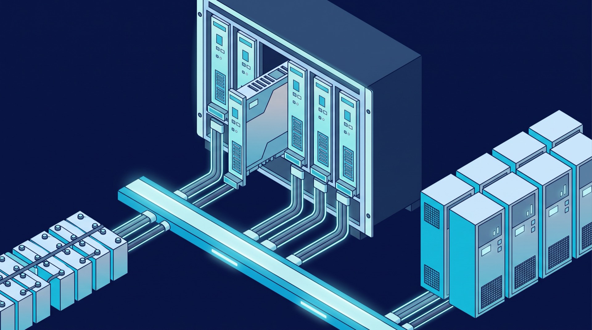
A modular plant is a subrack, a common DC busbar, a system controller, a distribution section and n identical plug-in modules. Each module is a complete converter — an active power factor correction stage feeding a DC/DC converter, with its own protection circuits and RS485 link to the controller. Nothing in the power path is shared but the busbar.
The commercial consequence is that capacity and redundancy are bought in the same increment: one more module is one more 3000W at 48V, or one more 1500W at 24V, and also one more spare. The modules are 1U and under 1.7kg, which is how the ETR3048 reaches up to 9000W in 1U of height and the ETR1524 up to 4500W. They share load without a master, current sharing held to ≤±5% of max current from 20% to 100% load, and they are hot-swappable, so the plant is expanded and repaired live.
The ESD Series industrial DC UPS answers the same brief differently: a floor-standing thyristor cabinet, 6-pulse on three phase with 12-pulse optional, covering 24VDC to 600VDC and 10A to 2000A behind a standard input isolation transformer. Its increment is the whole cabinet, so redundancy is bought by paralleling — its manual describes up to four units over CANBUS. Modular suits a growing 24V or 48V telecom bus; the cabinet suits a 110VDC or 220VDC switchgear board needing galvanic isolation more than granular growth.
Sizing a modular DC rectifier plant: load current plus battery recharge current
This is the step that gets skipped. A DC plant does two jobs at once — it feeds the load continuously and recharges the battery after every discharge — and one rectifier capacity has to cover both, because after an outage both demands arrive together. Work through it in this order:
- Total the continuous load current at the float voltage the bus will hold, not at the nominal voltage on the drawing.
- Add the switching and inrush duty that will genuinely coincide, not the arithmetic sum of every peak.
- Take the recharge current from the battery manufacturer's recommended charge current for the cells chosen. The rectifier cannot invent it: on the ESD Series the battery charge current depends on the battery capacity and is a settable current limit at the front panel.
- Add the two together. That total, in amps, is the plant rating.
- Divide by the per-module current at your float voltage — 56A at 53.5Vdc for a 3000W 48V module — and round up. That is N.
- Add the redundant modules on top of N, never inside it.
- Why an omitted recharge current does not announce itself
- Current limiting is a constant-current mode, not a trip: the ESD manual states that when output current reaches the current limit value, or battery current the battery current limit value, the unit reduces its output voltage to hold the current at the limit. In an undersized plant the load is served first, the battery gets what is left, and recharge stretches out — so autonomy stays degraded far longer than the outage that caused it, and nothing alarms, because nothing has failed.
What N+1 means when redundancy is counted in modules
Here N is the number of modules needed to carry load plus recharge at the design bus voltage, and +1 is one more of the same module in the next slot. Three checks belong in the specification.
Rounding up is not redundancy. If the sum needs three and a half modules you fit four and the plant looks as though it has a spare — but lose one and the remaining three are below requirement. Count the +1 after the rounding.
Temperature erodes redundancy. Both ETR module manuals state that above 55°C ambient the output power is reduced linearly up to a maximum of 75°C, above which the module shuts down and stays down until ambient falls below 65°C. An unventilated cabinet in August therefore has less headroom than the same subrack on a bench, and the redundant module's contribution is what disappears. Cooling is front-to-back, so an obstructed front face is also a derating.
Energy saving can put the spare to sleep: the ETR controller switches modules on and off to raise system efficiency, and the reserve it keeps online is a menu setting — the manual shows that mode field set to N+0. The logic of N+1 and 2N redundancy in AC UPS systems carries over, with the difference that a failed DC module is absorbed by the busbar rather than by a transfer. And a module that has lost communication has not stopped working: its green indicator stays on with only the yellow protection indicator flashing, which is why a lost rectifier and a failed rectifier are different alarms.
The system controller, and what happens when it fails
The controller does everything the modules cannot do alone. It commands module on/off switching, float and equalize charging, the module current-limit point and the output voltage setpoint; it monitors battery temperature, voltage and charge/discharge current; and it provides temperature-compensated charging, battery charge current limiting and low voltage disconnect. It draws its own supply from the DC bus — nominally 24Vdc or 48Vdc, working down to 18V and up to 60V at about 0.1A at 48Vdc — so it stays alive on the battery when the AC input has gone.
If it dies, there is no outage. Each module regulates its own output, and the controller manual's busbar-sensing fault entry confirms the fallback: where bus sensing disagrees with the average rectifier output voltage by 2.0V, the system bus voltage depends on the rectifier output voltage.
What stops is coordination and visibility — no temperature compensation, no scheduled boost, no battery charge current limit, no low voltage disconnect control and no remote alarms. In an unmanned hut that means the next battery problem goes unreported. The controller is hot-swappable, so treat it as an urgent replacement and keep the configuration documented: the manual warns that a missing or invalid profile causes a configuration error, and that a firmware upgrade can leave the serial baud rate changed.
Battery selection and the float and boost regime the rectifier must provide
The battery sets the charge regime and the rectifier has to deliver it, so the battery decision comes first. Design life divides the options: across the ENCLOVE industrial battery range, VRLA is rated at 10 to 12 years, OPzV at 15, OPzS at more than 15 and Ni-Cd at more than 20 years.
Whatever the chemistry, the plant must hold a precise float voltage, apply an elevated boost voltage on a timer and withdraw it, limit battery charge current independently of load current, compensate for battery temperature, and disconnect the battery before it is over-discharged. The ESD Series publishes exactly that: regulation of < 0,5%, a boost charge timer settable from 0 - 20 Hours at the front panel, a voltage adjustable range of 80% to 125% of nominal voltage, and battery protection covering temperature compensated charge, low voltage disconnect, battery current limit, MCB/MCCB and boost inhibit. Its manual moves the unit to equalize within 30 seconds of battery current exceeding the equalize-current setting, but only once 60 minutes have passed since the last successful equalize — so a charger apparently refusing a boost command is often inside that lockout.
Then the trap: the boost voltage the battery wants can exceed what the load tolerates, and the two share a busbar. The setpoint has to sit inside the module's own window — an ETR3048 adjusts to 58Vdc, but its output overvoltage protection latches above 59.7Vdc and needs a manual power cycle. And where the load cannot accept the elevated voltage the plant must drop it, which is why the ESD datasheet offers the load output as a diode dropper or a DC/DC converter: hardware chosen at order time, not configuration.
Monitoring an unmanned substation or telecom site
A DC plant is usually the least visited equipment on site and the one whose silent degradation costs most. The first question is which alarms you consume, not which the equipment can raise. The ETR controller separates a rectifier that has stopped talking from one that has failed, and one failure from several; it also flags rectifier current limit, system overload against a configurable threshold, battery over-current and current limit, battery fuse failure and low voltage disconnect. One deserves particular attention: a no-load alarm when total rectifier current falls below a configurable share of maximum system capacity — that is how you find a plant that has quietly stopped supplying while its battery carries the site.
The second is transport. The ETR controller offers serial, RS485, CAN and Ethernet, with web browsing and SNMP over the Ethernet port and alarms mapped across six digital outputs. The ESD Series ships with ModBus over RS232 and four settable volt-free contacts, and offers RS485, TCP/IP and IEC61850 — the last being what matters for substations and process plant feeding an existing SCADA system. A contact nobody wired is not monitoring.
Finally, keep the monitoring alive without AC: the ESD option for power supply redundancy from a DC source keeps the control system and display running when the input is absent. And set restart behaviour deliberately — the ESD manual prefers automatic start where attendance is difficult, and after a DC high alarm the unit resets 20 seconds later and retries up to four times, but if the last two events fall under 10 minutes apart it stops retrying and stays in alarm until someone attends.
What to settle before the purchase order
Each has a wrong answer that is cheap to fix on paper and expensive on site.
- The load current, at the voltage the bus will hold
- State which module figure the count came from — 56A at 53.5Vdc or 62.5A at 48.0Vdc — so the next engineer can check the arithmetic.
- The battery, its recharge current and the autonomy required
- Choose chemistry and capacity first, take the recommended charge current from the battery, and add it before counting modules. Recharge current is an input, not a consequence.
- The redundancy, counted in whole modules after rounding
- State N and the redundant modules separately, and confirm N alone covers the total at the highest ambient the enclosure will reach.
- The alarm contract, in writing
- Name the alarms that must reach the SCADA or network management system, the protocol they arrive on, and how the plant stays powered to report them.