What input current harmonics are, and why a rectifier draws them
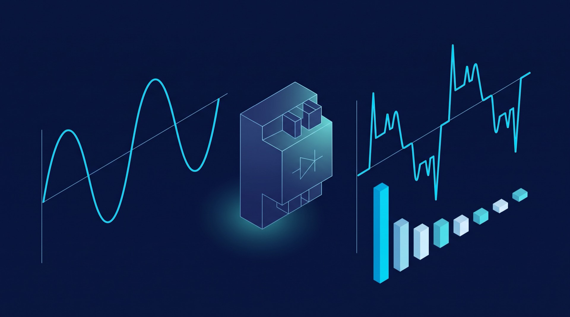
A linear load draws current in proportion to the voltage across it: sine wave in, sine wave out. A rectifier does not. It conducts only while the instantaneous supply voltage is favourable relative to the DC side it charges, so current flows in bursts around the voltage peaks and falls close to zero between them. The supply voltage stays sinusoidal; the current does not.
That non-sinusoidal current is a fundamental at supply frequency plus components at integer multiples of it — the harmonics. Total harmonic distortion of the current, THDi, expresses their combined content as a percentage of the fundamental: a description of the current's shape, not an amount of energy. Which orders appear follows from the topology's pulse number, which is why a 6-pulse and a 12-pulse bridge produce different families.
THDi is what the load draws; THDu is what the network then sees
Two quantities both get called harmonic distortion. THDi is current distortion — the shape of the current the rectifier draws. THDu is voltage distortion — the shape of the voltage on a bus. Current distortion becomes voltage distortion through the impedance of the source, so the same THDi barely troubles a stiff supply and badly troubles a weak feeder or a generator. THDi belongs to the machine and can be specified; THDu at a bus belongs to the machine plus the network, and no supplier can promise it alone.
Read the label carefully. The LEON-A datasheet lists its input distortion row as THDu, at 30%, with 12% using a 12-pulse rectifier and 5% with an input filter; the LEON-A manual gives current total harmonic distortion under 30% with an input power factor (nominal) of 0.8; and the datasheet's key features say the 12-pulse topology reduces input THDi and raises input power factor. When one percentage lands on a quotation, make the supplier state whether it is current or voltage distortion, and at what load.
Distortion at the point of common coupling is also subject to standards and to the network operator's connection conditions, so the applicable limits must be confirmed for the site. A standards list — EN 62040-1 and EN 62040-2 on the LEON-A — says what a product is built to, not that a limit is met at your intake.
What harmonic current actually costs you
Harmonic current does no useful work at the load and still has to be carried, so everything between the intake and the rectifier is affected.
- Transformer heating and derating
- Harmonic current raises copper loss, and because eddy-current loss climbs with frequency it raises core and winding loss disproportionately. The transformer runs hotter for the same delivered kilowatts, which shortens its life or forces a derate.
- Neutral current in a four-wire system
- Triplen harmonics do not cancel in the neutral of a three-phase four-wire system; they add. ENCLOVE's three-phase LEON-A models are wired 5W (3P+N+PE), and the LEON-A manual specifies a neutral cable current rating of 1.4 times rated current — the neutral of a rectifier feed is not a lightly loaded conductor.
- Cable derating and nuisance tripping
- Ratings and protection respond to rms and peak current, and distortion raises rms current for the same real power. Cable and breaker sizes end up driven by a current the kW figure never predicted, and a circuit inside its rating can still trip.
- Capacitor banks and resonance
- Correction capacitors and the supply inductance form a resonant circuit. If that resonance sits near an order the rectifier produces, the harmonic current is amplified rather than absorbed, and the capacitors are the first casualty.
Why a UPS that behaves on the utility misbehaves on the generator
This is the failure mode that surprises people at commissioning. A utility transformer is a comparatively stiff source; a generator is not. Its impedance is far higher, so the same harmonic current produces far more voltage distortion at its terminals. Nothing about the UPS has changed — the source underneath it has.
That distorted voltage feeds the generator's own regulation: the voltage regulator senses a waveform it was not designed to sense, and the governor holds speed against a current shape nothing like a resistor's. Frequency wanders, regulation degrades, and the UPS reads an input outside tolerance — so it drops to battery on a healthy generator, or refuses to transfer back.
Input windows are the first check: the EON 11 Series accepts 40-70Hz (46-54Hz @ 50Hz / 56-64Hz @ 60Hz) and lists perfect genset suitability alongside input power factor correction (PFC), while the EON 31 Series accepts 40~70Hz (Auto Sensing). The deeper fix is the front end, because THDi is what the generator turns into voltage distortion. An active front end at 5% or less looks nearly linear to a genset; a 6-pulse thyristor bridge at under 32% does not, and oversizing the generator to cope is capital cost the front-end choice could have avoided. Where genset interaction is the design case it shows in the data: the NSP Series shore power converters publish under 3% THDi at nominal load with an input power factor above 0.99.
The front-end options, from a plain bridge to an active rectifier
Four broad answers, and they are not interchangeable — they differ in distortion, cost, weight, footprint and how much of the result depends on the supply.
- Full-bridge and 6-pulse thyristor rectifiers
- Simplest, cheapest, most robust, most distorting. The ESD Series thyristor rectifiers publish THDi under 50% at a power factor above 0.7 for the single-phase full-bridge unit, and under 32% at above 0.8 (0.9 optional) for the three-phase 6-pulse one. The LEON-A's GPL11000 is full bridge; the GPL31000 and GPL33000 are 6 Pulse / 12 Pulse.
- A passive input filter
- A tuned filter or line reactor ahead of the bridge, and the cheapest large improvement available: the LEON-A publishes 5% with an input filter against 30% standard, the ESD Series optional values under 12% and 8%. It costs volume and weight, and it must be on the order.
- A 12-pulse rectifier
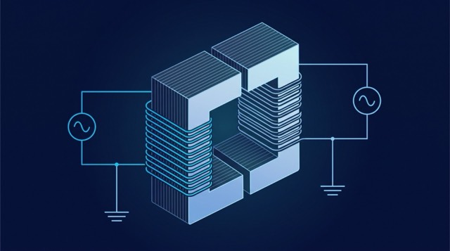
- Two completely separate rectifiers in parallel, the additional one fed through a phase-shift transformer sized for half the UPS power; the LEON-A manual says the arrangement reduces input current harmonics at higher power ranges. The LEON-A quotes 12% against 30% standard; the ESD Series offers 6 Pulse (OPT: 12 Pulse).
- An active PFC rectifier
- An IGBT front end drawing near-sinusoidal current in phase with the voltage, attacking distortion and displacement together. The EON 31 Series publishes input THDi of 5% or less at 0,99 or better, the EON 33 Series 1% or less for linear load across 10kVA to 60kVA; ENCLOVE's modular UPS range goes further, StratusPower at THDi<0.8% for linear load and THDi<3% for nonlinear.
Input power factor and THDi are two different claims
Power factor has two independent parts. Displacement is the phase shift between the fundamental current and the voltage; distortion is the harmonic content. A phase-controlled thyristor bridge is poor on both counts for different reasons: the LEON-A manual gives an input power factor (nominal) of 0.8 with current total harmonic distortion under 30%, and the ESD three-phase unit pairs a power factor above 0.8 with THDi under 32%. Because the two are fixed by different equipment, the distinction has commercial teeth — capacitors improve displacement, do nothing for distortion and risk the resonance above, whereas an active front end improves both, which is why the EON 31 pairs 0,99 with 5% or less.
So never read a power factor figure as evidence of low distortion. Ask for both, ask which definition of power factor is quoted, and ask at what load each was measured — the NSP and PROTEUS Series state under 3% THDi at nominal load, and the modular families quote separately for linear and non-linear load.
How to specify harmonic distortion so quotes are comparable
The underlying choice follows from the supply rather than the load, and every item below belongs in the schedule rather than in a conversation.
- State which quantity you are specifying — input current distortion at the equipment terminals, or voltage distortion at a named bus — and at which load points it must be met.
- Name the configuration: full bridge, 6-pulse, 12-pulse, passive input filter, or active PFC rectifier. On the LEON-A the 12-pulse rectifier and the input filter are options, so a quotation that stays silent is quoting the 30% figure.
- Ask whether a filter or phase-shift transformer sits inside the cabinet or arrives separately, with its own footprint, weight and losses.
- Ask what the front end does on standby generation, and record the assumed generator rating before the generator is ordered.
- Confirm the applicable limits with the network operator and the site's connection conditions. That is a site question, not a datasheet question, and it governs how much mitigation you buy.
- Require the measurement basis for every figure: load level, load type, supply voltage, and with or without the optional filter.