
How a datacenter power chain hands power along
Two clocks run through the chain, and confusing them is the most common design error.
The first is measured in milliseconds: how long a source can be absent before the load notices. A server power supply holds up briefly on its own internal energy, then drops. Anything slower than that hold-up time has, as far as the load is concerned, caused an outage — even if nothing in the room flickered. A generator and an electromechanical transfer switch cannot meet it; a UPS and a static transfer switch can.
The second clock is measured in minutes: how long stored energy lasts. It belongs to the battery, not the UPS, and no amount of UPS redundancy extends it.
The last thing to establish is where the paths converge. A design drawn as independent A and B routes is only dual-path up to the first component both routes share. Find that component and you have found the design's real availability limit, whatever the drawing claims.
Stage one: utility service and the site transformer
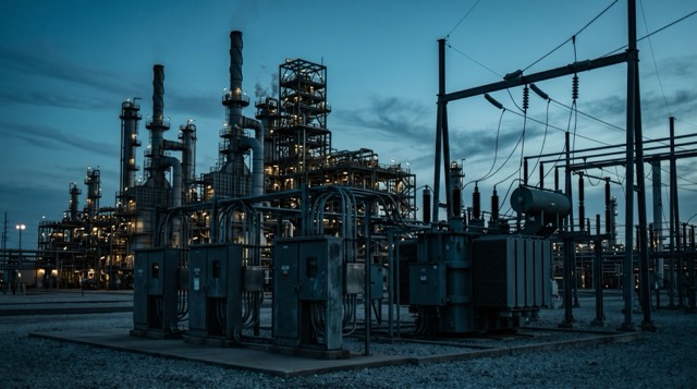
The chain begins with an incoming feeder, high-voltage switchgear and a transformer stepping the supply down to the low-voltage board. Everything downstream inherits this stage's quality, not merely its presence.
What fails: feeder faults from weather, excavation or upstream substation work; transformer failures, rare but measured in weeks of lead time rather than hours; protection that operates correctly on an unanticipated fault; and the quiet mode that trips nothing at all — voltage that sags, swells or distorts while remaining nominally present.
What that takes down: everything not downstream of stored energy, which almost always includes cooling. A utility event is rarely an IT event first — it is a mechanical event whose IT consequence arrives later, as heat.
What is available: a second feeder from a different substation, a second transformer, and a properly rated tie between low-voltage boards. Two feeds into one board is a supply improvement, not a redundancy claim — the board remains a single component. Sags and distortion are answered further down the chain: a double-conversion UPS accepts a 40-70 Hz mains input and, for loads below 100%, a voltage range of −25% to +20%, so shallow disturbances are absorbed without touching the battery. Feeding the hall through ENCLOVE UPS systems rather than raw mains turns a dirty supply into a non-event.
Stage two: the generator and the transfer switch that brings it on
When the utility goes, a standby generator becomes the site's source of energy. It does not become that source instantly, and the whole design lives in the gap.
What fails: start failure — starting battery, control panel, fuel quality, a valve somebody closed during maintenance. Then load acceptance: a set that starts cleanly can still trip on a block load or fail to hold frequency. Then the transfer switch itself, a mechanism with a duty cycle that on many sites has not moved under load since commissioning.
What that takes down: everything on the generator-backed board that is not also behind a UPS — cooling, lighting and often the site's own control power. The IT load rides through on stored energy; the room it sits in does not.
What is available: the choice of switching technology matters most here, and the three families behave very differently.
- Manual transfer switches require physical operator intervention to switch between power sources, resulting in a significant power interruption.
- Automatic transfer switches use electromechanical contactors to switch sources on detecting a failure, and the contactors physically moving means a genuine break in supply.
- Static transfer switches use solid-state thyristors to monitor both sources and transfer the load in less than 5ms.
- Why a brief break is not the same as no break
- Even a brief interruption is invisible to a lighting circuit, survivable for most motors, and long enough to reboot a server — which is why generator-side and IT-side transfer are usually different products. The ENCLOVE transfer switch range covers both roles, but an electromechanical switch is right for mechanical plant and wrong for a rack. Redundancy here otherwise means N+1 generator capacity, independent fuel paths, and a periodic transfer test under real load — a set that runs monthly but has never taken the building is untested.
Stage three: the UPS, the only no-break element in the chain
Everything upstream of the UPS can be interrupted and recovered. The UPS is the one stage whose job is to ensure the load never learns anything happened. In online double conversion the load is always fed from the inverter, so losing the mains changes only where the DC comes from — the three-phase EON 33 range is specified with a 0 ms transfer time.
What fails: the rectifier, the inverter, the DC bus capacitors, the fans, the control board or the firmware. Any of them can drop the unit onto static bypass, which is not a failure of the load but a total loss of protection — the load is now on raw mains and only the alarm system knows. Capacitors and fans are wear items that fail on a schedule — the modular platform publishes a DC capacitor life of >10 years and 15+ years caps with smart fans.
What that takes down: a single UPS with a single output path takes down, or silently unprotects, everything behind it. A UPS in maintenance bypass takes down nothing and protects nothing.
Efficiency figures need an operating mode attached: the modular families are quoted at 97.1% and 97.6% VFI efficiency in double conversion, against 99,4% on static bypass.
What is available: three approaches, which are not equivalent.
- Parallel or N+1 monolithic units
- Redundancy sits at the cabinet level, so the redundant capacity is a full unit and every maintenance event is a full unit's worth of work.
- Modular systems with module-level redundancy
- Modular UPS systems run from 10 kW to 3.75 MW with N+X redundant modules inside a frame. CumulusPower fits 1 to 10 modules per frame across a 10kW-3.6MW range, each module a complete UPS with its own converters, static bypass and control, so it isolates itself on an internal fault. The published availability for that architecture is 99.9999999% — a figure describing the UPS block, and only the UPS block.
- Industrial units chosen for the room
- Sometimes the environment drives the specification. The industrial UPS range covers 10-500kVA with a +25 years design life, for plant rooms where a commercial cabinet's filters and fans would not last.
Stage four: the battery is your real time limit, not the UPS
The UPS converts power; the battery stores energy. Runtime is a property of the battery, so every question about ride-through is really a question about the string.
What fails: a single weak or open cell takes the whole string offline, because a series string has no internal redundancy. Corroded terminals and loose links raise resistance until the string cannot deliver current when asked. Ambient temperature quietly consumes design life. And none of it shows on the front panel: a battery that has lost most of its capacity looks identical to a healthy one until the mains goes.
What that takes down: the entire protected load, at the moment the chain most needs it — the chain's only genuinely latent failure. Everything else announces itself.
What is available: multiple parallel strings, so losing one is a capacity reduction rather than a total loss; string-level monitoring and periodic discharge testing, because float voltage tells you almost nothing; and temperature control of the battery room.
Chemistry is a service-life decision more than a performance one. Across the ENCLOVE industrial battery range, VRLA blocks are quoted at 10-12 years of design life, OPzV cells at 15 years, OPzS at +15 years and Ni-Cd at +20 years. A modular UPS works with Lead-Acid/NiCad/Lithium strings at 360-480 Vdc built from 20-50 blocks or cells, charging at 20 A per module on the smaller frames and 40 A on the larger ones. Recharge time belongs in the calculation too.
Stage five: distribution boards and PDUs, where A and B quietly become one
Downstream of the UPS the chain fans out — output board, distribution board or busway, rack PDU, outlet. This is where redundancy is most often lost on paper rather than in service.
What fails: a breaker that trips upstream of where the fault actually is, because selectivity was never studied. A distribution board fault, rare but total. A busway tap or a PDU input termination. And the design failure no data sheet warns about — two redundant UPS systems whose outputs meet at a single downstream board, so one fault there takes both.
What that takes down: whatever the affected board feeds, and if coordination is wrong, considerably more.
What is available: keep A and B physically and electrically separate from the UPS output all the way to the rack — no shared board, no shared busway, no shared conduit — then run a selectivity and short-circuit study instead of assuming coordination. The numbers to coordinate with are published: a modular UPS output is specified for a 3 x IN short circuit capability and its bypass will pass <1000% overload for 100ms, while the inverter's overload profile of 124% continuous, 125% overload for 10 min and 150% overload for 1 min describes what the source will deliver during an event, not the load's steady-state draw.
Stage six: the static transfer switch, two paths for a single-corded load
At the rack the chain meets a commercial reality: much of the equipment ships with one power supply and one cord. A fully dual-path system then terminates in a single point of failure the facility team cannot redesign.
A static transfer switch resolves that: it takes two independent sources, monitors both, and moves the load to the alternate fast enough that its power supply never sees an interruption.
What fails: the switch is now itself in the critical path, so its own control and internal supplies matter — ENTS Series units carry up to four independent internal power supplies to remove that single point of failure. Transfers between sources out of synchronism take longer than synchronised ones, and a fault on the load side follows the load through the transfer.
What that takes down: only the loads it feeds — the argument for several small units rather than one large one.
What is available: static transfer switches with a break-before-make thyristor stage transfer in <5ms (Sync) and ~10ms (Unsync) at 50Hz, and <4ms (Sync) at 60Hz. The ENTS range spans 16A to 1200A in 1/2/3/4 pole configurations, at 94 - 99% efficiency with a 3:1 crest factor, and hot-swappable modules with full front access so a unit can be serviced without dropping the load. Protection covers backfeed, unsynchronised transfer and a bypass interlock, and the datasheet cites IEC 62310-1/2/3, written for static transfer systems.
One note outweighs all of that: a static transfer switch is only as good as the independence of its two sources. Fed from two boards sharing an upstream breaker, it merely adds a component.
The parts of the chain people forget
Walk a single-line diagram and you will account for every power component drawn on it. The failures that actually surprise people live in the things the diagram does not draw.
- Controls, monitoring and DC control power
- Breakers, transfer schemes and generator control panels need a supply of their own, usually DC — DC UPS and rectifier systems across the 24V to 600VDC spectrum exist for that job. If control power fails, a healthy chain can still fail to reconfigure itself. Monitoring is the other half: dry contacts, RS232, RS485, Ethernet and SNMP get UPS and switch state into the operations centre. Redundancy you cannot see cannot be proved.
- Cooling is part of the power chain
- Cooling is normally fed from the generator board rather than the UPS, so in the gap between utility loss and generator load acceptance the IT keeps computing while heat rejection stops. The power equipment has thermal limits too: the modular UPS is rated 0-40°C with no power derating and derates 1% for each additional 100 m above 1000 m; the ENTS static transfer switch is rated 0 to 50°C.
- The load has a shape, not just a size
- Modern IT load is non-linear, drawing current in short, high peaks. What fails is a load whose inrush or harmonic content exceeds what the chain was sized for, or whose hold-up time is shorter than the transfer time upstream; what that takes down is the load, and the source too if protection operates. The answer is to specify for the load's shape, not its average — a modular UPS output holds THDv<1% for linear load and THDv<3% for non-linear load at unity power factor (kW = kVA).
- A redundant path to a single-corded server is not redundant
- The most expensive misunderstanding in the chain. Two utility feeds, two generators, two UPS systems and two distribution paths still deliver one path of availability to a server with one power supply. Redundancy has to reach the load or it reaches nothing — either the equipment is dual-corded, or a static transfer switch at the rack makes two paths look like one to it.
How to review an existing power chain for its weakest link
Reviewing a chain is not an audit of components. It is a search for the point at which the redundancy story stops being true. A workable order of work:
- Obtain an accurate single-line diagram, then verify it against the plant as installed.
- Trace one critical load to the utility along both paths; the first component name on both lists is the availability limit.
- Count the components in that trace with no alternative: one transformer, one output board, one battery string, one cord.
- Compare battery age against quoted design life, and find when a discharge test was last run under real load.
- Identify which board feeds cooling, and calculate how long the IT load can run with heat rejection stopped.
- Confirm the date of the last full-load transfer test on the generator and every transfer switch.
- Check control power and monitoring for the same single points as the power path. One DC supply is one DC supply.
- List every load with a single cord and decide, for each, between dual-corded equipment and a static transfer switch at the rack.
- What the review should produce
- Not a score. A short list of named components whose failure would be visible to the business, with an explicit decision against each: accept, mitigate, or budget to remove. It is also the most useful thing to bring to a supplier — a diagram plus a list of accepted risks produces a specification, while a kVA figure produces a quotation. Send yours to the ENCLOVE engineering team.